Carlo Kopp, Monash University
August 14, 2012
Active Electronically Steered Array (AESA) X-Band radars are now the baseline in state of the art combat aircraft, progressively displacing legacy Mechanically Steered Arrays (MSA) and Passive Electronically Steered Arrays (PESA) in most new designs and some block upgrades of existing designs. The technology is now penetrating into other areas historically dominated by MSA and PESA technology, including Airborne Early Warning radars, Surface to Air Missile engagement radars, and volume search radars. This trend will continue for a number of very compelling reasons, which will be further explored.
The AESA is not a panacea for all radar applications and imposes a number of unique requirements on supporting hardware, which are lesser or indeed absent, in many legacy radar technologies. These requirements amount to costs in systems integration, which matter to varying degrees across applications. What is abundantly clear is that AESAs will become the dominant technology in many high volume radar applications over the coming years, as the technology matures and manufacturing costs progressively decline. To best appreciate why the AESA has been so successful, it is worth first exploring the evolution of ESAs or “phased arrays.”
Evolution of Electronically Steered Array Radar Technology
The first “modern” operational production phased array radars were the German VHF-Band GEMA FuGM41 Mammut or “Hoarding” series of air and sea surveillance radars, deployed during the latter part of the Second World War.1 These revolutionary radars introduced the idea of electronic or “agile” beam steering, whereby the direction of the antenna main lobe was controlled not by physically pointing the antenna boresight, but by altering the relative phase or delay of the signals passing through elements in an antenna array. Earlier British “Chain Home” radars, decisive during the Battle of Britain, exploited phase relationships between pairs of antenna elements for direction finding, but the Mammuts were the first volume production designs to employ the idea of transmitting and receiving through an array of individual phase or delay controlled elements.2
This presented a major advantage, in that the physically large and heavy antenna, necessary for high gain at such long wavelengths, did not have to be mechanically pointed to sweep across a volume of space. Agile beam steering via electronic control of beam direction remains the principal advantage of ESAs over MSAs, as it permits flexible control of beams for tracking individual targets or groups of targets, as well as scan rates over volumes of space. The penalties for designers and maintainers were complexity, volume and weight, compared to MSAs. Until recently, complexity, volume and weight have remained the principal obstacles to wider use of ESA technology. The need for complex feed networks, individual phase or delay control components, and supporting control hardware, is reflected accordingly.
The 1970s saw important advances in ESA technology, with the development of a number of important systems in the United States and the Soviet Union. In all instances, the motivation was the ability to track large numbers of fast targets concurrently, to support missile guidance applications, whether defending against tactical or strategic ballistic missiles, or cruise missiles at low or high altitudes.
In the critical strategic ballistic missile acquisition and tracking role, the 450 MHz Raytheon FPS-115 Pave PAWS3 and Soviet 150 MHz NIRI 5N15 series Dnestr/Hen House ESA radars were developed and deployed.4 The later Pave PAWS variants delivered an average power of 145.6 kW, and peak power of 582.4 kW, using no less than 1,792 array elements, each rated at 325 W.
The U.S. Army/Raytheon C-Band MPQ-53 Patriot engagement radar and the Soviet X-Band 5N63/30N6 Flap Lid S-300PT/SA-10 Grumble and 9S32 Grill Pan S-300V/SA-12 Giant/Gladiator engagement radars were also PESAs, all developed to engage aircraft, cruise missiles, standoff missiles and tactical ballistic missiles. All three also shared the same design approach, using a passive optical space feed and transmissive primary antenna array of phase shift elements. The Soviet designs used an elaborate monopulse feed horn arrangement, placed behind a lens assembly.5
A similar space feed arrangement was adopted in the Soviet X-Band 9S19 Imbir/High Screen ABM acquisition radar, developed for the S-300 V/SA-12 Giant/Gladiator system, and the Janus-faced S-Band NIIIP 5N64/64N6 Big Bird battle management radar developed for the later S-300PM/SA-20A Gargoyle.6
Similar operational requirements drove the development of the U.S. Navy’s S-Band RCA SPY-1 Aegis PESA radar, with each antenna face comprising 4096 elements, divided into 140 modules, each with 32 elements, and complex feed network of waveguides to distribute transmit and receive signals. The SPY-1A qualified as a hybrid array, with 4352 solid state receivers embedded in each antenna face, and employed eight transmitters for a total of 132 kW peak power per face.7
Features shared by this generation of ESA radars were the use of passive transmissive ferrite technology phase shift elements and Travelling Wave Tube (TWT) transmitter stages, often ganged to increase total peak power. Optical space feeds were preferred in weight sensitive applications such as land based missile batteries, unlike the Aegis system and lower band BMD radars, which used feed networks. Variants or derivatives of all these radars remain in operational use and production today.
The 1980s saw a second generation of ESA radars emerge, for airborne applications, leveraging experience gained by designers during the early 1970s. In the United States, Westinghouse developed the X-Band APQ-164 radar for the B-1B Lancer bomber, a PESA design derived from the EAR demonstrator, which shared a single 1,526 element aperture for ground mapping, weapon targeting and automatic terrain following waveforms, with some Low Probability of Intercept (LPI) capabilities. The APQ-64 employed a redundant pair of TWTs, and redundant receiver chains, to match the reliability of the ESA antenna.8
It was soon followed in development by the Hughes Ku-Band APQ-181 LPI PESA “covert strike radar,” developed for the B-2A Spirit stealth bomber. While the APQ-181 used similar antenna technology to the APQ-164 and provided similar navigation, targeting and automatic terrain following capabilities, an additional and challenging requirement was that the structural mode Radar Cross Section of the antenna face had to be compatible with the “small bird sized” signature of the host aircraft.9 The APQ-181 demonstrated a critical advantage of ESAs over MSAs, which was compatibility with low observable applications, a key long term driver of demand for AESAs, especially in airborne applications.
While early U.S. effort in airborne ESA radar focused on bomber radars, the first Soviet airborne X-Band PESA was the 1,700 element Tikhomirov NIIP BRLS-8B Zaslon or Flash Dance pulse Doppler air intercept radar, developed for the large MiG-31 Foxhound interceptor. This aircraft had the challenging role of intercepting low flying Boeing AGM-86B cruise missiles, GD BGM-109G Gryphon ground launched and RGM-109 naval cruise missiles. The Zaslon was built to concurrently guide four long range R-33 Amos missiles against low signature targets in ground clutter, and was the first volume production ESA fitted to a fighter aircraft. An interesting feature was that an L-Band IFF interrogator PESA was embedded in the X-Band array.10
Like the first generation of surface-based ESAs, features shared by this generation of ESA radars were the use of passive transmissive ferrite technology phase shift elements, and Travelling Wave Tube transmitter stages, but antenna feed networks were employed, typically in stacked row structures. Many ideas first employed in these radars have since been employed in AESAs.
PESA technology continues to be used in a number of new production Russian designs, including the hybrid ESA Tikhomirov NIIP N011M BARS radar in the Su-30MKI/MKM Flanker H fighter, the derivative N035 Irbis E radar in the Su-35S Flanker fighter, the Phazotron Zhuk-MFS/MFSE PESA for the Su-33 Flanker D naval fighter, the Leninets B004 multimode attack radar for the Su-34 Fullback bomber, modelled on the APQ-164, and the NIIP Ryazan GRPZ Pero PESA upgrade package for the N001VE Flanker radars. The Pero is curious insofar as it is a reflective space feed design, with an X-Band horn on a boom placed in front of the array. The technology is also used in the X-Band 9S36 engagement radar developed for the new 9K317 Buk
M2/SA-17 Grizzly battlefield air defence missile system.11

Fig. 1 Comparison of PESA and AESA designs.
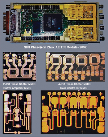
Fig. 2 Phazotron Zhuk AE X-Band quad module and MMIC chips.
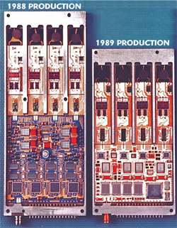
Fig. 3 Early U.S. developed quad T/R module technology.
The 1990s saw a progressive transition in the United States and EU to AESA designs in key applications, with Russia and China now following. While the new AESAs exploited much of the technology previously developed for PESA radars, they introduced fundamentally different transmitter technology. The critical enabler was the maturation of GaAs planar monolithic processes, which permitted the production of power transistors and monolithic phase shifters. GaAs MESFETs with low noise figures (NF) for low power receiver applications were widely available 25 years ago, but AESAs did not become feasible until MMIC technology became mature enough to package the necessary volume of circuitry into Transmit-Receive Module (T/R module) volumes of sizes compatible with critical applications. That point was reached 15 years ago for L-Band and S-Band applications, and a decade ago for more challenging X-Band applications. Figure 1 shows a comparison of PESA and AESA designs, based on typical X-Band airborne radars. Whereas the PESA employs passive phase shift elements, the AESA T/R modules combine multiple MMICs to produce independently controlled receivers, transmitters and beamsteering controls, usually by phase. Figure 2 shows a Phazotron Zhuk AE X-Band Quad Module and MMIC dies, developed in 2006-2007. The Russian industry lags the United States in T/R module design, but can be expected to close the gap rapidly. Figure 3 shows an early United States quad module technology versus current single channel T/R module technology. Single channel modules permit better production yields in comparison with quad modules or multichannel “stick” designs.
At this time, AESA technology has penetrated into a number of key application areas, encompassing X-Band airborne and fire control radars, early warning and search radars between the VHF-Band and S-Band, and specialised S-Band and X-Band BMD radars. AESAs are appearing both as technology insertion upgrades into established operational radars, but also as entirely new designs displacing legacy radars.
In airborne applications for fighter and bomber aircraft, dominated by X-Band designs, the first volume production AESA was the 1,500 element Westinghouse, now Northrop-Grumman, APG-77 for F-22A Raptor. This radar was the trend setter in technology and is now in its second configuration, the APG-77(V)1 which uses common modules to the smaller 1,200 element APG-81 developed for the F-35.12
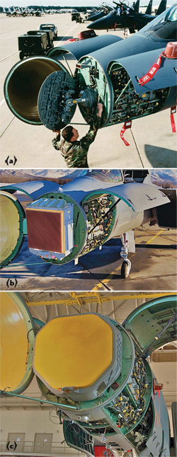
Fig. 4 Evolution of the F-15 X-Band AESA radars.
A parallel development was the 1,100 element Raytheon APG-79, developed initially as a block upgrade to the extant APG-73 in F/A-18E/F Super Hornet, but eventually evolving into a unique design. The T/R module technology developed for the APG-79 was exploited for the subsequent APG-63(V)3 AESA upgrade to the F-15C and APG-82(V)1 AESA radar upgrade for the F-15E. Figure 4 shows the evolution of F-15 X-Band AESA radars. Early F-15 radars employed TWT driven MSA technology, exemplified by the APG (a). Some F-15Cs were later retrofitted with the early APG-63(V)2 AESA, which employed “stick” technology T/R modules (b). The most recent upgrade involves the APG-63(V)3/APG-82 configuration using single element T/R modules, based on the APG-79 design (c). The T/R module technology also migrated into a deep upgrade of the APQ-181 which, in its AESA incarnation, uses a pair of 2,000 X-Band element arrays. Northrop-Grumman concurrently developed the 1,000 element APG-80 as a block upgrade or new build design for the competing F-16 fighter, the APG-80 evolving into the Scalable Agile Beam Radar (SABR) design.13
While combat aircraft dominate the U.S. airborne X-Band AESA effort, the AN/ZPY-2 Multi-Platform Radar Technology Insertion Program (MP-RTIP) was launched, specifically to provide a dedicated surveillance imaging and Ground Moving Target Indicator capability, intended for the E-8 JSTARS, E-10 MC2A and RQ/MQ-4 Global Hawk. The MP-RTIP X-Band radar was intended for ISR. Figure 514 shows a production RQ-4B Block 40 Global Hawk Remotely Piloted Vehicle, which will carry the MP-RTIP AESA under a ventral radome (a), and a prototype carried by the Scaled Composites Proteus demonstrator (b). AESA technology will also be central in the design of the Next Generation Jammer (NGJ) support jamming podset for the EA-18G Growler, intended to use GaN components.15
European manufacturers lagged behind the U.S., but now offer several X-Band AESA products, including the Thales AESA RBE2 for the Dassault Rafale fighter, replacing the initial PESA design, the Euroradar Captor-E (ECR-90) for the Typhoon fighter, and the smaller Selex Vixen 500E and 1000E AESA radars, the latter intended for Gripen NG. All designs leveraged experience gain in the collaborative Airborne Multirole Solid State Active Array Radar (AMSAR) program.16
Phazotron was the first Russian manufacturer to offer an X-Band AESA with the Zhuk AE for the MiG-35 Fulcrum fighter in 2007, soon followed by the competing Tikhomirov NIIP with a larger AESA for the SU-27/30 Flanker fighter, and the low observable Sukhoi T-50 PAK-FA.17
An interesting parallel development is a Tikhomirov-NIIP L-Band AESA intended for embedding in the leading edges of fighter wings and strakes, providing a dual role IFF and Counter Low Observable capability.18
There have been no disclosures of substance on China’s X-Band AESA technology, but it is known that the J-10B fighter has a radar bay shape and is sized for an APG-82 class AESA. While fighter applications are predominantly in the X-Band, the Northrop-Grumman AN/ASQ-236 AESA Radar Pod is a Ku-Band design developed specifically for precision ground mapping.19 While X-Band AESAs for combat aircraft remain numerically dominant, AESAs penetrated into the Airborne Early Warning radar market during the 1990s. Israel’s IAI/Elta developed the L-Band EL/M-2075 Phalcon on a Boeing 707-320, later selling the demonstrator to Chile. The technology evolved into the EL/W-2085 radar carried by the G550 airframe and is currently flown by Israel and Singapore.20
The same technology was offered unsuccessfully to Australia in 1998 for the Wedgetail requirement, then sold to China, the order later cancelled under pressure from the Clinton Administration. Eventually India procured the system, with a three sided EL/W-2090 L-Band AESA installed inside a fixed radome, carried on a Beriev modified Ilyushin Candid airframe designated the A-50EI.21 Sweden has been highly successful in exporting its S-Band Erieye family of AEW&C radars, supplied to Sweden, Brazil, Greece, Mexico, Pakistan, Thailand and the United Arab Emirates and carried on commuter sized airframes, jet or turboprop.
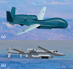
Fig. 5 The MP-RTIP X-Band radar is a scalable design intended for ISR applications.
The only new U.S. AEW&C AESA design is the Northrop-Grumman L-Band Multi-Role Electronically Scanned Array (MESA) system, developed commercially and sold to Australia, Turkey and South Korea on the Boeing 737-600 airframe. Figure 6 shows the Northrop-Grumman MESA radar. Operating in the L-Band, the design combines a pair of side looking arrays, with a cavity endfire array to provide coverage over the nose and tail, in a surfboard shaped “tophat” radome.22

Fig. 6 Northrop-Grumman MESA radar.
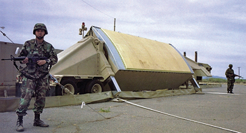
Fig. 7 AN/TPY-2 THAAD-GBR/FBX-T radar.
The cancellation of the Israeli order led China to initiate the development of the KJ-2000 system, which is modelled on the three sided EL/W-2090 L-Band AESA, and has been supplied to the PLA Air Force, on the Ilyushin Il-76 Candid airframe. The PLA Navy has been procuring the KJ-200, itself modelled on the Swedish Erieye design.23
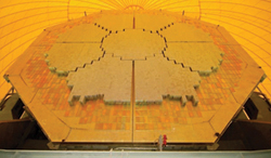
Fig. 8 The 22-meter diameter, 45,056 element SBX radar.
While airborne applications have been the primary target for AESA developers, niche surface based applications are seeing increasing use. One of these is acquisition and fire control radars for missile defense applications. The first of these was the Israeli L-Band Elta EL/M-2080 Green Pine, developed to support the Arrow ABM. It was soon followed by the 25,344 element X-Band Raytheon AN/TPY-2 Theater High-Altitude Air Defense Ground-Based Radar/Forward-Based X-Band - Transportable (THAAD-GBR/FBX-T) wideband AESA, (see Figure 7) developed as an acquisition and engagement radar for the THAAD anti-ballistic missile system. The largest and most powerful AESA in this domain is the 45,056 element Sea Based X-Band (SBX) radar, developed for the Ground-Based Interceptor (GBI) three stage exo-atmospheric ABM – the AESA antenna face is 22 meters in diameter (see Figure 8).24
X-Band acquisition and fire control radars for defending warships against sea skimming cruise missiles are another domain where AESAs have become prominent and will be central to the intended Air and Missile Defense Radar (AMDR) competition. Known examples include the Raytheon AN/SPY-3 Multi-Function Radar (MFR) developed for the Zumwalt class destroyer and Ford class carriers, the 3,000 element four-sided Thales Active Phased Array multifunction Radar (APAR) deployed on the Dutch De Zeven Provinciën class FFG and German Sachsen class FFGs, (see Figure 9), and the Australian CEA Technologies 1,024 element CEAFAR/CEAMOUNT system developed for the ANZAC (Meko) class FFGs, (see Figure 10) – all are intended to guide the RIM-162 Evolved Sea Sparrow Missile.25
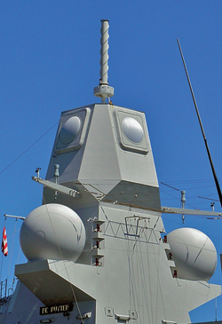
Fig. 9 A 3,000 element four-sided THALES APAR.
Search and acquisition radars are also seeing increasing use of AESA technology. The Thales/Raytheon Groundmaster series S-Band GM200 and GM400 are good examples, as was the developmental S-Band component of the Zumwalt’s Dual Band Radar (DBR) system. The Chinese S-Band Type 305A/K/LLQ305A appears to be fundamentally influenced by the Thales designs.26 No less interesting are the Russian Almaz-Antey/NNIIRT 1L119 Nebo SVU and 55Zh6ME RLM-M Nebo M VHF-Band three-dimensional Counter Low Observable search and acquisition radars, (see Figure 11). The former employs 84 elements, each with 1.4 to 1.7 KW power ratings, the latter employs 168 elements, possibly of higher rating.27 At this time, it is abundantly clear that AESA technology has invaded all traditional mainstream niches in military radar.
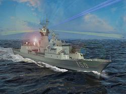
Fig. 10 Australian CEA technologies 1,024 element CEAFAR/CEAMOUNT system developed for the ANZAC (Meko) class FFGs.
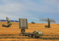
Fig. 11 Russian Almaz-Antey/NNIIRT 55Zh6ME RLM-M Nebo M VHF-Band three-dimensional counter low observable search and acquisition radar.
The Advantages and Limitations of Active Electronically Steered Arrays
There are some compelling reasons why AESAs are displacing PESA and MSA designs and will eventually relegate the latter to specialised niches.28 The first and foremost is beam forming and beam steering agility which, in contemporary designs, permits changing beam parameters at rates of up to kilohertz. This was the initial imperative in early ESA applications, as the antenna could track multiple targets with very high update rates, critical when intercepting fast targets like supersonic cruise missiles and aircraft, or re-entering warheads.
A byproduct of this agility is the ability to “timeshare,” “multiplex” or “interleave” the antenna between different tasks. In fire control applications, this permits concurrent tracking of widely separated targets, or concurrent search and missile midcourse guidance or terminal guidance. In search applications, it permits the ability to concurrently perform volume searches while tracking and, in surveillance applications, the ability to interleave surface mapping and moving target detection. In combat aircraft, it offers the ability to interleave mapping, terrain following or avoidance, air target and surface target searches and data linking. A single AESA equipped multimode radar can thus replace two or more legacy single function radars.
The second critical driver is that AESAs are much more reliable than traditional radars, primarily due to the use of hundreds to thousands of independent T/R modules – the failure of even large numbers of T/R modules only degrades antenna performance. Catastrophic AESA failure only arises when a shared subsystem like a power supply or beam steering controller (BSC) fails. MSAs on the other hand are exposed to mechanical component wear out failures, and single point failures in highly electrically stressed components like TWTs, waveguides, feeds and high voltage supplies.
An important advantage of AESAs over PESAs is the ability to independently control per-element gain as well as phase. This has important impacts in several areas:
The first is that beam forming can be more precise and different taper functions can be applied for different beams. This is most commonly used in side lobe suppression, which is a long running issue in clutter and jammer rejection, but more recently in achieving stealth, as very low side lobes reduce the probability of detection by hostile intercept or surveillance receivers. Other byproducts of this capability include the ability to make design trades between wavefront planarity in the main lobe, versus side lobe magnitude, or generate nulls within the main lobe to reject jammers.
AESAs can potentially be built with much greater bandwidth than PESAs or MSAs, facilitating Low Probability of Intercept (LPI) modes and enabling functions such as Electronic Attack (jamming) against in-band emitters. This capability is also exploited in some designs to permit the use of a radar AESA as an additional high gain antenna for a threat warning subsystem, or a data link with bandwidth potential of Gigabits/second, or LPI/covert capabilities, or both.
AESA receivers typically enjoy a 6 dB or better noise figure advantage over PESA/MSA receivers, as the loss between the antenna radiating element and first receiver stage contributes to the net noise figure or system level noise temperature. Higher power aperture AESAs also have significant potential as Directed Energy Weapons, to produce disruptive or electrical damage effects in electronically dense target systems.29 Fixed AESAs are inherently better than gimballed MSAs in terms of structural radar cross section, which makes them inherently compatible with stealth vehicles, airborne or other.
These advantages do not come for free. Complexity and development costs are higher for AESAs versus MSAs. Weight and volume can be significantly higher than MSAs. Power consumption and cooling are major issues for AESAs and have often presented “brick wall” barriers to integration in smaller platforms. Power density limitations in the semiconductor devices and T/R module level cooling architectures can set hard limits on AESA performance growth in many designs. AESAs are software intensive with rigid real-time processing demands, presenting many unique engineering challenges well outside the RF domain, with much potential for software gremlins and outright functional failures.
From a raw gain performance perspective, AESAs must confront the problem of aperture foreshortening for targets well off the antenna boresight, and hard limits on beam steering angles between 45° and 70°. Phase steered AESAs also suffer intrinsic bandwidth limitations arising from aperture fill and side lobe steering effects, which impact all high bandwidth demand applications, with varying severity.30 In many applications, the only solution compatible with low structural RCS is the use of multiple AESA installations, incurring concomitant penalties in cost, complexity, weight, volume and cooling. Examples include the planned for but never fitted F-22A cheek arrays, or planned T-50 PAK-FA cheek arrays. AESAs are not a panacea for all microwave antenna applications, but present significant advantages in most applications, advantages which justify additional penalties incurred in using the technology.
Active Electronically Steered Array Technology Trends
The technology driving advances in AESA design is without doubt monolithic device technology, which determines bounds on power-aperture performance of AESAs, directly via power transistor performance and indirectly via cooling performance. The latter is also heavily impacted by packaging technology, which imposes limits on density and cooling systems.
The GaAs MMIC was the enabling technology for AESAs in the S-Band and above, and also the reason why L-Band AESAs were early entries in airborne applications as these were the least dependent on transistor fT performance. The poor thermal performance of GaAs substrates, despite the excellent carrier mobility in the material, has been a persistent problem through much of the history of the AESA, and has been a strong imperative for the use of materials with better thermal properties, such as SiGe, or especially GaN.31 Packaging techniques have also evolved dramatically since the first X-Band AESA demonstrators were built. Array design theory dictates element spacing of a half wavelength or less, which presents increasing density challenges with increasing frequency. The contemporary power density benchmark is exceeding 4 W/cm2 at the array face.
Early U.S. X-Band AESA designs and current Russian designs used a “stick” or “quad element” packaging design for T/R modules, with a single module containing a row or column of elements or channel in a “stick” or four in a quad. This approach presented persistent problems in production repeatability, as a defect in any channel required a rework of the whole stick or quad module, if that was feasible. Contemporary U.S. and EU AESAs employ a “single channel” approach where each element employs a stack of components (tile approach) normal to the antenna face. Backplane feed networks also present design challenges, especially in loss performance and bandwidth, despite the advantage versus the PESA in not having to handle high power levels. In X-Band designs, the feed network may incur further complexity due to the need to segment the array to create multiple phase centers to accommodate dual plane monopulse tracking or GMTI displaced phase centres (DPCA).
A single channel or element in an AESA must contain an LNA for the receive path, a power amplifier, a phase shifter, impedance matched low insertion loss interconnections, gain control blocks, RF buffer amplifiers if required, as well as the digital circuits and control logic required to latch downloaded gain and phase parameters into the T/R module phase shifter and gain control components. Modern AESA T/R modules will also include circuits for health monitoring and Built-In-Test (BIT), and calibration.
Heat from semiconductor components in the T/R module must be conducted out of the module and carried out of the antenna using a cooling system. X-Band AESAs typically employ a Poly-Alpha-Olefin coolant, dumping heat into aircraft fuel, or via a heat exchanger into surrounding air.
In assessing futures for AESA technology, advanced RF device materials and processes will comprise one part of the equation and exponentially growing density in photolithographically fabricated digital components is the other part. Brookner has recently identified the following benchmarks and trends in device and materials technology:32
Arrays using micro-electrome- chanical systems (MEMS) phase shifters
Low cost 24 GHz phased-array car radars driving down T/R module costs through volume
Extreme MMIC circuitry for 8 to 32 element arrays on single SiGe/BiCMOS chips
GaN technology offering tenfold higher power and higher efficiency, permitting >1000 W peak power with single transistor packages
Low cost Silicon based SiGe single chip
Purdue University low-cost S-Band two panel GaN Digital Array Radar having 700 MHz bandwidth, 25 W per element peak; gets wide angle scan through use of electromagnetic band gap (EBG) material for increased isolation between antenna elements (lower mutual coupling); has potential of eliminating circulator
Arrays with instantaneous bandwidths of 10:1 up to 33:1
20 dB increased receiver dynamic range through improved A/D linearity and reduced intermodulation
Exploitation of meta-materials in passive antenna components
3D micromachining technology for interconnections
Exponential density growth is a well documented feature of the digital landscape, but is less prominent in RF components, due to the encumbrances of impedance matching and need for analogue components.33 Growth, especially in parallel processing computer hardware, will impact radar across all categories, by providing abundant capability to perform floating point arithmetic. Current General Purpose Graphics Processing Unit (GPGPU) chips have internal memory bandwidths in excess of 100 Gigabytes/sec and often in excess of 500 pipelined floating point optimized processing cores in a single chip. Density growth in this technology will yield larger numbers of cores and higher memory bandwidths, enabling signal and data processing algorithms which are currently computationally infeasible in realtime applications.
In conclusion, continuing advances in MMIC materials and fabrication technologies, advancing packaging technology and exponential growth in digital circuits open many possibilities for future AESA designs.
http://www.microwavejournal.com/article ... technology